Arduino Mood Lamp / LED Cube

I wanted to build an Arduino mood lamp that worked without any buttons and is customizeable for any mood / light situation. So I did a little research and found about the posibility to trigger input on the Arduino with something called “capacitive sensing” and began to design a lamp with 3 input sides which are separate from each other. That led to the idea that it would also be exciting to control each LED of each side of the cube individually with different mood-modes.
So I saw a little cube which could do these things:
- Each side of the cube should be controlled individually
- Minimalistic handling (no buttons, except on/off)
- User should be able to
- Change the “mood mode”
- Change the color
- Change the saturation
So I began tinkering… 😉
The Electronics
As every project the mood lamp started on the breadboard with lots of wire chaos.
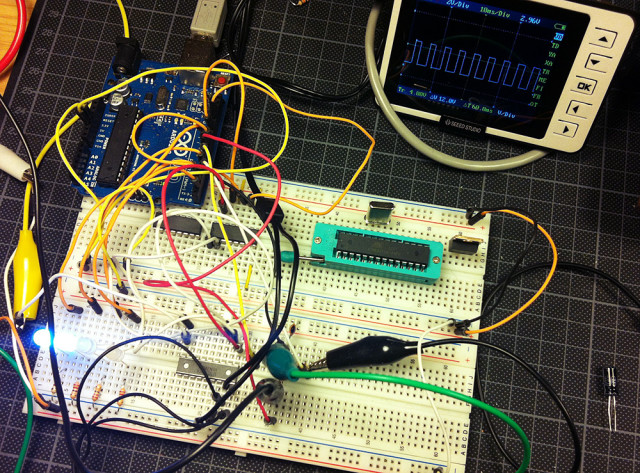
As you can see in the image above it was necessary to check if the Arduino and the 74HC595 are outputting the PWM signal needed for the RGB LEDs. One RGB LED needs 3 PWM ports and since I wanted each side to be controlled individually I needed 5×3 = 15 PWM ports. Unfortunatly the Arduino – ATMega328 – only has 6 PWM ports. So I used the ShiftPWM library to emulate PWM on digital pins through port expanding it with the 74HC595 shift register.
For the first time my DSO Nano oscilloscope from Seeed Studio became really handy to see whats going on in these tiny wires.
Since the RGB LEDs needed 12V it was necessary to use a darlinton array (ULN2803) – transistor array – to switch the LEDs from 5V logic to the needed 12V voltage.


Of course the breadboarded concept was then transfered to a standalone Arduino ATMega328 on a perfboard and soldered together.
The device needed a case…
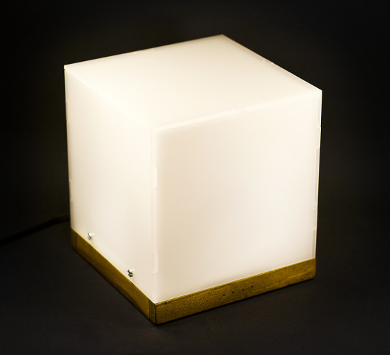
The Case
I designed the case with a wooden base frame with 4 status LEDs in the front. Each LED has just a very small hole to enhance the minimalistic style. Each side of the LED cube got its own “cell” so each side could be controlled individually.

It was the first time that my DIY mini CNC machine was used to produce parts for another project. Very nice feeling when you really can utilise something you´ve build before. 😉


The wooden frame has been hand cut, glued and then coated with a dark wood stain to contrast the light “milky” Plexiglas surface. All holes and cuttings for the switch, status LED sockets and the power wire have been cut/carved with my Dremel CNC.
All other plastic parts also have been cut with my mini CNC. The Plexiglas has been cut with a laser CNC at the FabLab in the city where I live.
The Software
The cube uses the great ShiftPWM library to controll the RGB LEDs as well as the the CapSense library.
The navigation in the “cube menu” is as follows:
- Front: Change Mode
- Left: Up (+)
- Right: Down (-)
So moving your hand before the front changes the mode. On the left side you go down, on the right side you go up in the “menu”.
The front LEDs show you in which mode you are:
- LED: Change color in RGB for all sides
- LEDs: Change saturation
- LEDs: – Empty –
- LEDs: Change Mode
- Continuos
- Relax (Each side slowly fades randomly, one color)
- Color Shift (fades through all RGB values)
- Party (each side fades through all RGB values after each other, fast)
Conclusion
It was a lot of fun building this one learned a lot about RGB LEDs and “capacitive sensing” as well as building and planning cases.


I named this project “RelaxCube” because I do really like the “Relax Mode” the most. Looking forward to use this knowledge for further projects! 🙂
Further reading
Capacitive Sensing
CapacitiveSensor for Arduino
ShiftPWM library